

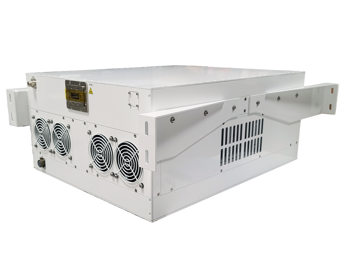
A solid-state power amplifier, commonly shortened to SSPA, is an RF amplifier that increases the power of a radio frequency signal using semiconductor technology.
In satellite communications, an SSPA is used on the ground-based transmit side of the RF chain. Its role is to raise the signal to the power level required before it is fed to the antenna for uplink transmission.
For earth stations, teleports, and other satcom ground infrastructure, the amplifier forms an important part of the transmit path. It needs to deliver sufficient RF power while maintaining the signal quality, efficiency, and reliability required by the wider system.
At ETL Systems, our focus is on the ground segment. We design and manufacture RF equipment used between the antenna and modem, including high-power amplification, RF distribution, frequency conversion, signal routing, and redundancy equipment.
The function of an SSPA becomes clearer when viewed as part of the wider ground-station uplink chain.
What Does a Solid-State Power Amplifier Do?
An SSPA takes a relatively low-power RF signal and increases its output power before transmission.
Within a typical satellite ground station, the transmit chain may include several stages. Signals can be routed, converted to the required uplink frequency, amplified, and ultimately fed towards the antenna.
The SSPA performs the high-power amplification stage.
The International Telecommunication Union’s guidance on fixed-satellite service systems identifies the power amplifier as one of the major subsystems within an earth station, alongside the antenna, receiver, monitoring, and terminal equipment.
Depending on the architecture, amplification and frequency conversion may also be combined within a block upconverter, or BUC. A BUC can accept a lower-frequency input, convert it to the required transmit frequency, and provide amplification before the RF signal reaches the antenna.
Our guide to RF frequency converters for satellite ground-segment applications explains this part of the uplink path in more detail, including how frequency conversion fits into ground-based satcom infrastructure.
Where Does an SSPA Sit in the Ground-Segment RF Chain?
An SSPA should be considered as part of the complete uplink chain rather than as a standalone component.
A simplified uplink path may look like this:
- The modem generates the communications signal.
- RF equipment routes and conditions the signal.
- Frequency conversion moves the signal to the required uplink band where necessary.
- The SSPA increases the RF power.
- The amplified signal passes to the antenna for transmission.
The exact architecture varies between ground stations.
In some deployments, the SSPA is installed indoors within an equipment room. In others, an outdoor amplifier is positioned much closer to the antenna.
This choice affects more than the location of a piece of equipment. It can influence waveguide requirements, rack space, accessibility, and the wider RF architecture.
How Does a Solid-State Power Amplifier Work?
An SSPA uses semiconductor devices to increase RF signal power.
SSPAs can use semiconductor technologies including gallium nitride, or GaN, and gallium arsenide, or GaAs.
Rather than relying on a vacuum tube to produce the required amplification, an SSPA uses transistor-based amplifier stages.
At a simplified level, the amplification process involves:
- receiving the RF input signal
- amplifying it through semiconductor stages
- combining RF power where multiple amplifier devices or modules are used
- managing the heat generated during amplification
- delivering the higher-power RF signal at the output.
For higher-power systems, multiple amplifier devices can be combined to achieve the required total RF output.
The engineering challenge is not simply to produce more watts. The amplifier must also preserve the characteristics of the transmitted signal while meeting the operating requirements of the wider link.
Why Is GaN Used in Modern SSPAs?
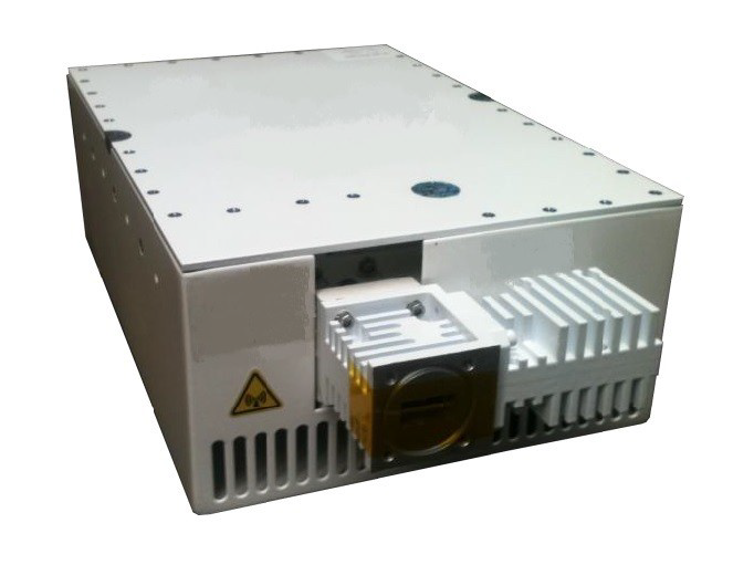
Gallium nitride has become an important technology in high-power RF amplification.
GaN’s growing adoption in RF power amplification is driven by its underlying semiconductor properties. A NIST review of RF and analogue semiconductor technologies describes GaN devices as offering substantially higher breakdown voltage and microwave power density than traditional GaAs or silicon devices.
These properties make GaN particularly relevant where engineers need to achieve substantial RF output within a practical equipment footprint.
For ground-based satcom systems, GaN technology can support characteristics including:
- high RF power density
- compact amplifier construction
- the potential for high linear RF performance
- practical outdoor configurations
- reduced equipment footprint
- reduced maintenance requirements in applications where a solid-state design replaces equipment with an RF power tube.
Our high-power amplifier range includes both solid-state and travelling wave tube technologies, allowing amplifier selection to be based on the RF and deployment requirements of the ground application.
SSPA vs TWTA: What Is the Difference?
Solid-state power amplifiers and travelling wave tube amplifiers, or TWTAs, perform the same broad function within an uplink: they increase RF signal power for transmission.
The principal difference is the technology used to create that amplification.
| Consideration | SSPA | TWTA |
| Amplification method | Semiconductor devices | Vacuum tube technology |
| Typical technology | GaN or GaAs | Travelling wave tube |
| Physical format | Can provide a compact, lightweight form factor | Can be larger depending on power and frequency |
| Maintenance | No RF power tube requiring periodic replacement | Tube life forms part of maintenance planning |
| Operating voltage | Solid-state electronic architecture | Requires high-voltage circuitry |
| Linearity | Can offer high linearity, depending on design and operating point | Depends on amplifier design and operating point |
| High-power capability | Increasing with developments in solid-state technology | Well established for demanding high-power applications |
Neither technology is automatically the right choice for every ground station.
Required RF power, operating frequency, bandwidth, linearity, efficiency, installation environment, resilience and lifecycle requirements all influence amplifier selection.
The question is therefore not simply whether an SSPA is “better” than a TWTA. The more useful comparison is which technology best meets the requirements of the particular uplink system.
Understanding Output Power and Psat
One specification deserves particular attention when comparing SSPAs: output power.
Amplifiers are often described using their saturated output power, usually written as Psat.
Psat describes the RF output available as an amplifier approaches saturation. It should not automatically be treated as the normal operating power available for every signal.
As an RF power amplifier approaches saturation, its behaviour becomes increasingly non-linear. Depending on the modulation and system requirements, the amplifier may therefore need to operate below its maximum saturated output.
This is known as output back-off.
An ETSI technical report on satellite communications link performance discusses amplifier non-linearity as a factor affecting link performance and considers back-off as one method of reducing non-linear effects.
For system designers and operators, headline wattage is therefore only part of the picture.
The more useful question is often:
How much usable linear RF power does the amplifier provide at the operating point required by the system?
That distinction can materially affect amplifier selection.
What Should You Consider When Selecting an SSPA?
An SSPA needs to fit the complete ground-station architecture.
Frequency band
The amplifier must support the required uplink frequency and bandwidth.
ETL Systems’ SSPA portfolio includes configurations for C, X, Ku, and Ka-band ground applications.
Required output power
Amplifier selection should be based on the link budget and the RF power required at the intended operating point, including any necessary back-off.
Selecting solely on maximum wattage can give an incomplete picture.
Linearity
Linearity describes how closely the amplifier maintains the characteristics of the input signal as its power is increased.
The required performance depends on factors including the modulation scheme and operating point.
Efficiency and thermal management
Not all electrical input power becomes useful RF output.
Some is converted into heat, meaning efficiency affects electrical consumption, cooling requirements, and thermal design.
These factors can become particularly significant in high-power installations.
Indoor or outdoor installation
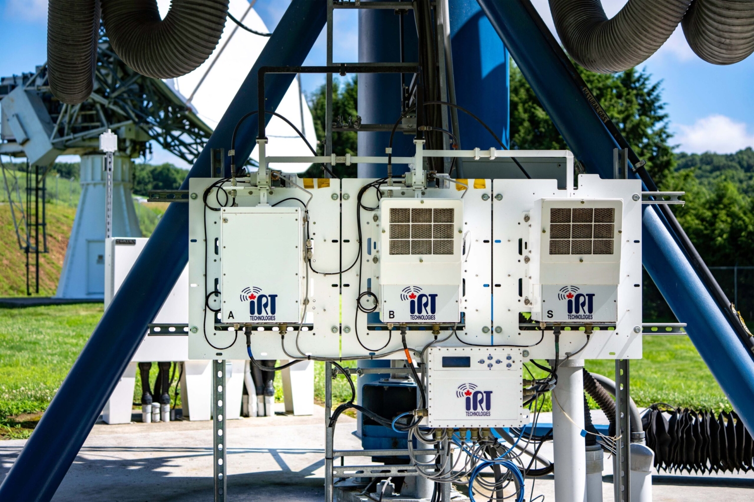
An indoor rack-mounted SSPA can integrate easily with other ground equipment, while an outdoor unit allows high-power amplification to be positioned closer to the antenna.
A practical example is ETL Systems’ 1.5 kW C-band GaN BUC/SSPA, introduced in 2025. Its outdoor configuration was developed to allow high-power amplification to be positioned closer to the antenna, reducing the need for long waveguide runs, while an indoor rack-mounted configuration is also available.
This illustrates why amplifier location is an architectural decision as much as a product specification.
Monitoring and redundancy
For mission-critical infrastructure, operators also need to consider how the amplifier will be monitored and how the link will respond if equipment becomes unavailable.
Depending on the system design, redundancy configurations such as 1:1 or 1:2 can provide an alternative amplification path if a primary unit cannot remain in service.
Monitoring and redundancy should therefore be planned as part of the RF architecture rather than treated as additions after the amplifier has been selected.
Where Are Ground-Based SSPAs Used?
SSPAs can be used across satellite ground applications where RF signals need to be transmitted reliably at higher power.
Examples include:
- fixed earth stations
- satellite teleports
- VSAT ground networks
- broadcast contribution systems
- digital satellite newsgathering
- government and defence communications
- transportable and mobile ground terminals.
Requirements vary considerably between these environments.
A large teleport may place particular emphasis on availability, monitoring and redundancy. A transportable ground terminal may give greater priority to equipment size, weight and ease of deployment.
In each case, amplifier selection is governed by the RF and operational requirements of the ground system.
Selecting an SSPA as Part of the Complete RF System
Selecting an SSPA is ultimately a system-level decision that begins with the complete ground-station architecture.
Frequency and maximum power matter, but they should not be considered independently of the rest of the RF chain. The amplifier needs to work with the modem, signal routing, frequency conversion, antenna infrastructure, redundancy systems, and monitoring environment.
For that reason, specifying an SSPA means looking beyond the maximum output figure on a datasheet.
Key considerations include:
- required usable RF power
- frequency band and bandwidth
- modulation and linearity requirements
- indoor or outdoor deployment
- thermal and electrical efficiency
- remote monitoring
- redundancy
- integration with the wider RF system.
At ETL Systems, we design and manufacture ground-segment RF equipment for signal management between the antenna and modem, including SSPAs for satellite uplink applications. Our focus is on how amplification operates as part of the complete ground infrastructure, rather than simply on the maximum RF power a unit can produce.
If you are specifying or upgrading the amplification stage of a satcom ground system, explore our solid-state power amplifier solutions to review the indoor and outdoor configurations available for different RF architectures.
For help discussing your system requirements or selecting suitable amplification equipment, contact the ETL Systems team to speak with one of our experts.