
1. Introduction
Satellite ground stations, whether a major teleport hub, a remote VSAT terminal, or an Electrical Ground Support Equipment (EGSE) test rack, depend on RF frequency converters to bridge the gap between the baseband/IF equipment and the high-frequency signals required for satellite uplinks and downlinks. Selecting the right converter for a given application requires an understanding of both the system architecture and the key performance parameters that govern converter behaviour.
This white paper is aimed at RF engineers and system integrators involved in the specification, procurement and deployment of frequency converters for professional satcom ground segments. It covers the underlying principles of frequency conversion, the most important specifications and what they mean in practice, the ITU frequency plan, and a guide to the ETL Systems FALCON converter family.
2. Fundamentals of Frequency Conversion
2.1 What Does a Frequency Converter Do?
A frequency converter, also called a block up-converter (BUC) for the transmit path or a block down-converter (BDC) for the receive path, translates a band of signals from one frequency range to another, preserving all of the modulation and information content of those signals. The conversion process uses a mixer driven by a local oscillator (LO). The mixer multiplies the incoming signal with the LO to produce sum and difference products:
|
RF_out = LO ± IF_in Upconverter output frequency = Local Oscillator frequency ± Intermediate Frequency input |
An output band-pass filter then selects the desired sideband (either LO + IF or LO – IF) and rejects the unwanted image product, the LO feedthrough and any other spurious signals.
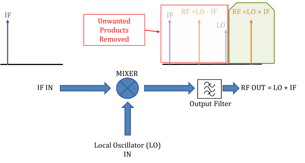
| Key concept: The mixer produces TWO sidebands
When LO and IF signals are mixed, the output contains both an upper sideband (LO + IF) and a lower sideband (LO – IF). The output filter selects the wanted sideband; both sidebands carry the same information but at different frequencies. The unwanted sideband is called the image. |
2.2 Common Ground Segment Applications
Frequency converters appear at several points in the ground segment signal chain:
- Transmit (Uplink) path: Earth station modems or modulators produce signals at a standard IF (typically 70 MHz, L-Band 950–1950 MHz, or extended L-Band up to 2150 MHz). An upconverter translates this IF to the satellite uplink frequency: C-Band (5.925–6.725 GHz), Ku-Band (13.75–14.5 GHz), Ka-Band (27.5–31.0 GHz), etc. before it reaches the high-power amplifier (HPA) feeding the antenna.
- Receive (Downlink) path: Satellite signals in C, Ku, K or Ka-Band arrive at the earth station antenna. After low-noise amplification (LNA), a downconverter translates the signal to IF or L-Band for onward connection to a satellite modem or demodulator.
- Test and EGSE: Laboratory test racks and Electrical Ground Support Equipment use converters to simulate satellite frequency plans and provide controlled RF stimulus for equipment under test.
2.3 Block vs. Synthesised (Agile) Converters
A fundamental choice in converter selection is between block (fixed LO) and synthesised (agile) types:
| Feature | Block Converter | Synthesised (Agile) Converter |
| LO frequency | Fixed — set in factory | Electronically tunable, user-selectable |
| Output frequency range | Fixed — translates entire input band as a block | Variable — operator selects centre frequency |
| Frequency step size | N/A (block translation) | Typically 1 kHz or finer |
| Phase noise | Generally better: simple fixed oscillator | Slightly Higher: synthesiser PLLs add phase noise |
A block converter with a fixed LO at 9.75 GHz, for example, will translate the entire 10.70–11.70 GHz Ku-Band downlink to 950–1950 MHz L-Band simultaneously. An agile converter operating over the same RF band allows the operator to tune the LO so that only a narrower band of interest is centred within the IF passband, useful when monitoring individual transponders or performing spectrum analysis.
3. Key Performance Specifications
Interpreting a frequency converter data sheet requires a clear understanding of each specification. The parameters below are the most important for ground segment applications.
3.1 RF and IF Frequency Range
The RF frequency range defines the input band for a downconverter (or the output band for an upconverter), while the IF range defines the corresponding IF port frequency span. Both must be aligned with the satellite frequency plan and the earth station equipment. For a fixed-satellite service earth station, the RF frequency will be one of the ITU-allocated bands described in Section 4.
3.2 Conversion Gain
Conversion gain (or loss) specifies how the signal level changes from the input port to the output port, expressed in dB. Professional converters typically provide positive gain (amplification) so that the output signal is delivered at a usable level. Gain flatness across the passband (typically specified as ± x dB across the band) determines how uniformly different frequencies within the band are treated. Poor flatness causes inter-symbol interference and degrades link performance in wideband multi-carrier systems.
3.3 Noise Figure
Noise figure (NF) quantifies the signal-to-noise ratio (SNR) degradation introduced by the converter, expressed in dB. For a receive chain, the overall system noise figure is dominated by the first active stage (usually an LNA), but the converter NF still contributes. The Friis formula shows that the converter NF contribution is reduced by the gain of stages preceding it:
| F=F_1+ (F_2-1)/G_1 + (F_3-1)/(G_1 G_2 )+ (F_4-1)/(G_1 G_2 G_3 )+…
NFdB = 10log10(F) Friis formula for cascaded noise figure (linear ratios) |
| Why noise figure matters
In professional satellite systems, signals arrive at the earth station antenna at very low power levels, often only a few dB above the thermal noise floor. Even small increases in system noise figure directly reduce link margin, potentially causing outages during periods of rain fade or satellite edge-of-coverage conditions. A lower NF is always preferable in a downconverter. |
3.4 Phase Noise
Phase noise describes the short-term frequency instability of the local oscillator, appearing as noise ‘skirts’ spreading out around the LO carrier on a spectrum analyser. It is specified in dBc/Hz (decibels relative to the carrier, measured in a 1 Hz noise bandwidth) at specific frequency offsets from the carrier.

For example, a specification of −85 dBc/Hz at 10 kHz offset means the noise power spectral density 10 kHz away from the carrier is 85 dB below the carrier.
Phase noise is transferred from the LO to the converted signal. For an upconverter, this degrades the spectral purity of the transmitted carrier, potentially violating regulatory emission masks or causing adjacent-channel interference. For a downconverter, it degrades the receiver’s ability to demodulate high-order modulation schemes (e.g., 16APSK, 32APSK) and increases the bit error rate (BER). High-order modulation schemes used in DVB-S2X and modern HTS systems are especially sensitive to phase noise.
| Phase noise and modulation order
As modulation order increases (QPSK → 8PSK → 16APSK → 32APSK), the constellation points move closer together, reducing the noise margin. A phase noise floor that is acceptable for QPSK may cause unacceptable performance degradation with 32APSK. Always verify phase noise performance against the modem’s specifications. |
3.5 Linearity: P1dB and OIP3
A frequency converter, like any active RF device, exhibits nonlinear behaviour at high signal levels. Two related parameters characterise this:
- P1dB (1 dB compression point): The output power at which the converter gain has decreased by 1 dB from its small-signal (linear) value. Above P1dB the converter is in compression: gain decreases, harmonics and intermodulation products grow, and the signal is distorted. Always operate converters well below P1dB, typically 6–10 dB back-off for multi-carrier operation.
- OIP3 (Output Third-Order Intercept Point): A theoretical figure-of-merit for linearity, derived by extrapolating the fundamental and third-order intermodulation (IM3) curves until they intersect. OIP3 is approximately 10 dB above P1dB for most converters. Higher OIP3 means lower intermodulation distortion for a given output power. It is especially important in multi-carrier ground stations where many transponder signals are present simultaneously.
|
IM3(dBc) ≈ 2 × (OIP3 – P_out_per_tone) Third-order intermodulation product level relative to a single carrier (for two-tone stimulus) |
3.6 Return Loss and VSWR
Return loss (expressed in dB, higher is better) and VSWR (Voltage Standing Wave Ratio, lower is better) both describe how well the converter input/output impedance is matched to the standard system impedance (usually 50 Ω). Poor impedance matching causes signal reflections that result in insertion loss ripple, potential instability in the chain, and signal integrity problems.
3.7 Spurious Outputs
A converter’s output will contain, in addition to the wanted converted signal, a range of unwanted spurious products including LO feedthrough, harmonic products (2×LO, 3×LO, etc.), and mixer intermodulation products. Spurious outputs are specified in dBc (dB below the carrier) and must be sufficiently low to satisfy regulatory emission limits and avoid interfering with adjacent transponders or system equipment. Key spurious products to check include:
- LO breakthrough to the RF output
- Image frequency response (see Section 3.9)
- Half-IF spur
- 2nd and 3rd order mixer products
3.8 Frequency Inversion
Frequency inversion (also called spectral inversion) occurs in a single-conversion downconverter when the LO frequency is above the RF input (i.e., IF = LO − RF). In this case, the relative positions of frequencies within the band are reversed at the output: the highest input frequency maps to the lowest IF frequency, and vice versa.
Whether or not a converter inverts the spectrum depends on the conversion topology (high-side or low-side LO injection). A non-inverting converter uses IF = RF − LO (LO below RF), so the spectral ordering is preserved. Dual-conversion architectures (see Section 3.10) typically yield a non-inverting response. All ETL Systems FALCON converters are non-inverting.
| Why frequency inversion matters
Satellite modems and demodulators are sensitive to spectral inversion. If the converter inverts the spectrum but the modem is not configured to compensate, the signal will not demodulate correctly. Always confirm whether the converter is inverting or non-inverting and configure the modem accordingly. |
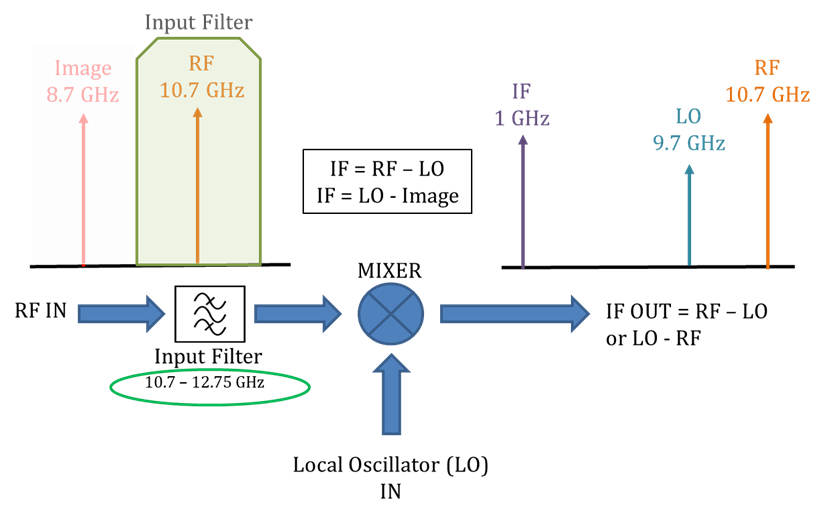
3.9 Image Frequency and Image Rejection
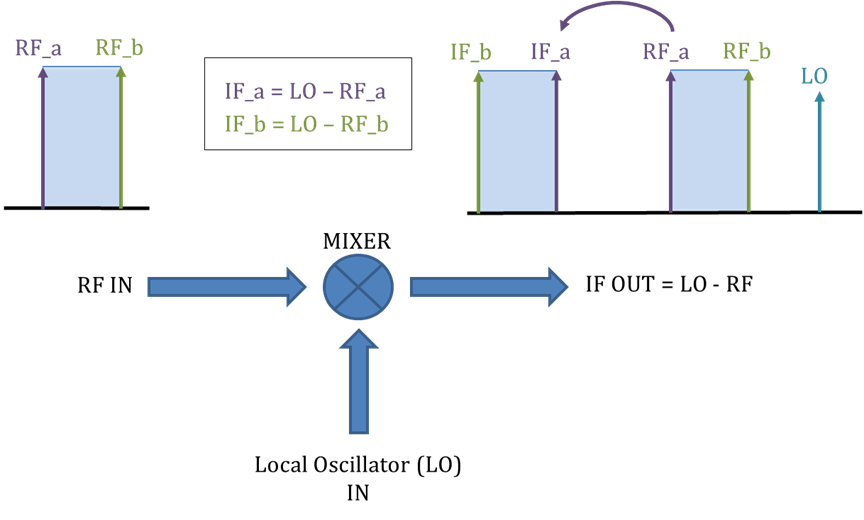
In any single-frequency-conversion receiver, for every wanted input frequency RF there exists an image frequency (RF_image = LO − IF for high-side LO, or LO + IF for low-side LO) that also mixes down to the same IF. An input signal at the image frequency is therefore indistinguishable from the wanted signal once it has passed through the mixer — it cannot be filtered out at the IF. The only way to suppress it is with a band-pass filter before the mixer.
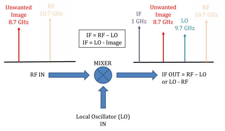
Image rejection is the ratio (in dB) of the converter’s response to the wanted RF frequency versus the response to the image frequency. High image rejection is achieved by ensuring the image frequency falls well outside the input filter’s passband. In some converter designs — particularly when the IF is a significant fraction of the RF — the image falls within the input filter passband and single-conversion topologies are inadequate; dual conversion must be used.
3.10 Single vs. Dual Conversion
A single-conversion converter uses one mixer stage. This is simple and cost-effective but may suffer from image or LO contamination when the IF is a large fraction of the RF (because the image is close to the RF). A dual-conversion converter uses two cascaded mixer stages with an intermediate frequency between them. This allows:
- First conversion: Translates the RF to a high intermediate frequency (IF1), ensuring the image frequency for the first conversion falls well outside the input filter.
- Second conversion: Translates IF1 to the final IF, again with adequate image separation.
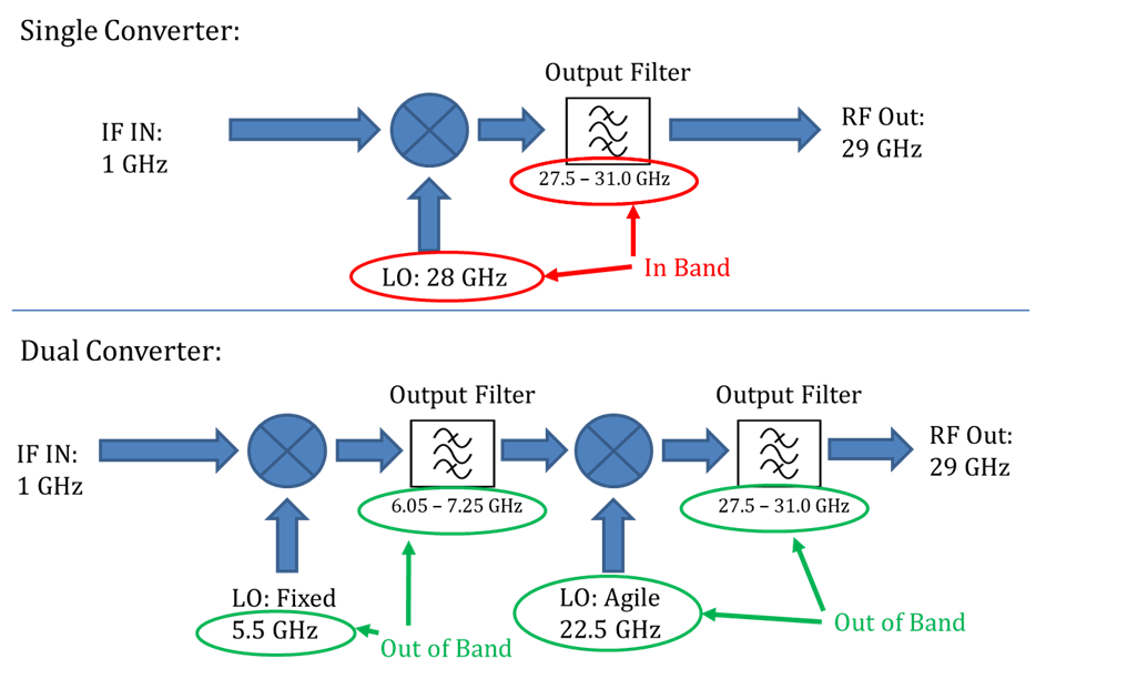
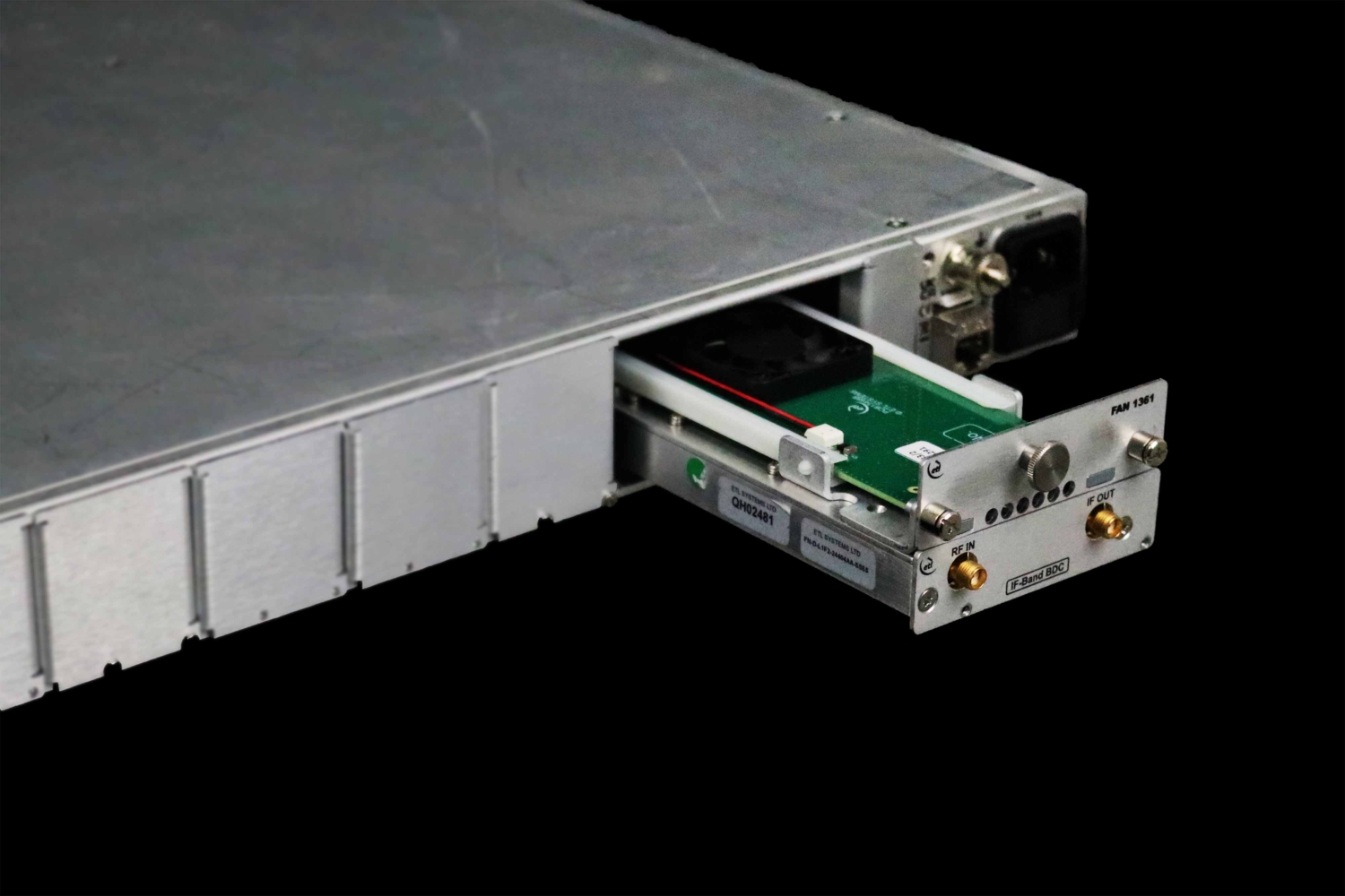
Dual‑conversion topologies require two LOs and two sets of filters, increasing cost and complexity. ETL’s Falcon2 converters use a dual‑conversion architecture where dictated by the frequency plan, delivering superior image rejection and supporting applications where performance is non‑negotiable.
| Parameter | Single Conversion | Dual Conversion |
| Complexity | Low | Higher |
| Cost | Lower | Higher |
| Image rejection | Limited by input filter | Excellent — image well out of band |
| LO count | 1 | 2 |
4. Checklist for Ground Segment Engineers
When specifying a frequency converter for a satcom ground segment application, work through the following checklist:
4.1 Frequency Plan
- Identify the satellite RF band (C, X, Ku, K, Ka, Q, V)
- Confirm whether uplink (Earth-to-Space) or downlink (Space-to-Earth) or both are required.
- Determine the IF/L-Band interface required by the modem or associated equipment (70 MHz, 140 MHz, L-Band 950–1950 MHz, etc.).
- Confirm the full RF frequency range and the required instantaneous bandwidth.
- Determine whether a block converter or synthesised (agile) converter is required.
4.2 Performance Requirements
- Noise Figure: Determine the system noise budget and maximum permissible NF contribution from the converter.
- Phase Noise: Check the maximum tolerable phase noise mask at relevant offsets (1 kHz, 10 kHz, 100 kHz). Higher-order modulation requires lower phase noise.
- Linearity (P1dB / OIP3): For multi-carrier operation, determine the maximum combined input power and required back-off. Calculate the required OIP3 from the number of carriers and the permissible IM3 level.
- Gain and Gain Flatness: Confirm the output level matches what downstream equipment expects, and that gain flatness is sufficient for the occupied bandwidth.
- Spurious outputs: Check regulatory emission masks and adjacent transponder separation.
- Image Rejection: Ensure adequate image suppression, particularly for wide-IF applications.
- Frequency Inversion: Confirm whether the modem can compensate for spectral inversion, or ensure the converter is non-inverting.
4.3 System Integration
- Connector types: Confirm RF connector type (SMA, 2.92, etc.) and IF connector requirements.
- Impedance: Standard 50 Ω throughout; verify VSWR/return loss.
- 10 MHz reference: Confirm whether an internal or external 10 / 100 MHz reference is required and the reference signal quality (phase noise, stability).
- Remote monitoring and control — Confirm required interface (Ethernet, SNMP, etc.)
- Physical: Confirm rack unit height, depth, and slot requirements.
4.4 Availability and Redundancy
- Determine the required system availability target and identify if redundancy is needed.
- Select 1+1 (one active, one standby) or 2+1 (two active paths, shared standby).
Streamline your operations with advanced frequency converter solutions.