
RF over fibre is a method of transporting radio frequency signals through optical fibre rather than carrying them entirely over coaxial cable.
In a satellite ground system, an electrical RF signal is converted into an optical signal, transported through fibre, then converted back into RF at the other end. The recovered signal can then continue through the rest of the ground-station equipment.
This is particularly useful when antennas and processing infrastructure are separated by distances that make a continuous coaxial run less practical.
At ETL Systems, our focus is the ground segment between the antenna and modem, where RF over fibre forms part of the terrestrial signal transport infrastructure.
Why Move an RF Signal onto Fibre?
Coaxial cable remains appropriate for many RF connections, especially over shorter distances. As cable length and operating frequency increase, however, attenuation can become a more significant part of the RF link budget.
RF over fibre changes the transport medium rather than the purpose of the signal. The RF information is carried optically for part of the route, allowing equipment to be separated without carrying the RF electrically across the full distance.
This can be useful across a teleport, between an antenna field and an equipment building, or in any situation where site layout makes long RF cable runs impractical. Fibre does not replace the RF system; it provides the transport path between RF equipment at either end.
What Actually Happens to the Signal?
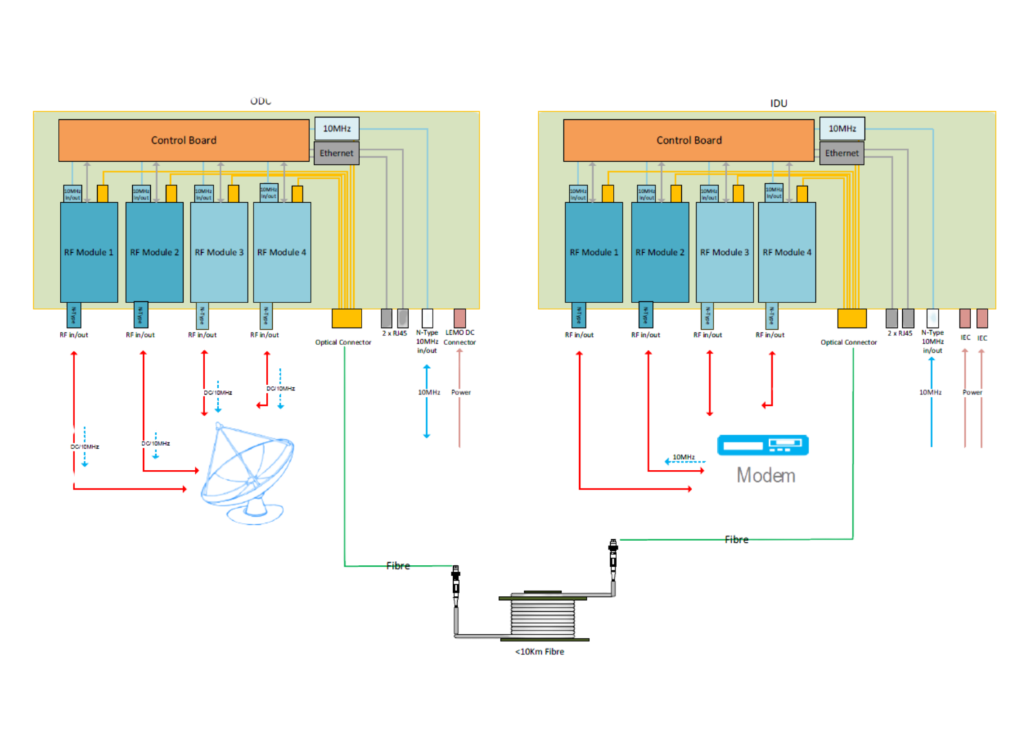
The signal path illustrates how the optical link operates.
1. The RF signal enters the optical transmitter
The process begins with an electrical RF or intermediate-frequency signal.
That signal needs to arrive at the RF-over-fibre transmitter within the equipment’s specified input range. This matters because the optical link must operate within the wider RF level plan.
2. Electrical RF is converted into an optical signal
A laser provides an optical carrier. Depending on the system design, the incoming RF waveform modulates that optical carrier so the RF information can be represented in light.
The ITU-R guidance on RF signal transport through optical fibres describes this basic architecture using electrical-to-optical conversion at the transmitting end and optical-to-electrical conversion at the receiving end.
The signal’s function does not change. Only the transmission medium does.
3. The optical signal travels through fibre
Once converted, the modulated optical signal travels along the fibre route.
This avoids carrying RF electrically for the full distance, where coaxial attenuation could otherwise become a significant part of the link budget.
Fibre is not loss-free. Attenuation occurs along the optical path, while connectors, splices, and passive optical components introduce additional losses.
4. The receiver converts the light back into RF
At the far end, an optical receiver detects the incoming light and converts it back into an electrical RF signal.
That recovered signal can then continue through equipment such as switches, matrices, frequency converters or modems.
5. The complete link is levelled
The recovered RF level, frequency response, noise and linearity still need to match the requirements of the downstream equipment, so gain planning forms part of the design from the outset.
RF Over Fibre Has Two Link Budgets
RF over fibre requires both an RF budget and an optical budget.
The RF budget
On the RF side, engineers may need to consider:
- input and output power levels
- total link gain
- noise figure
- linearity and intermodulation performance
- gain flatness across the required band
- the number and relative levels of carriers being transported.
Meeting the distance requirement is not enough if the recovered RF signal does not suit downstream equipment.
The optical budget
The optical side presents a different set of variables:
- fibre length
- operating wavelength
- fibre attenuation
- connector and splice losses
- passive splitters
- wavelength multiplexers and demultiplexers
- transmitter output and receiver sensitivity.
The current ITU-T G.652 recommendation for single-mode optical fibre defines transmission characteristics including attenuation and chromatic dispersion for widely used single-mode fibre.
Maximum distance is only a headline figure; usable length depends on losses in the actual route.
RF Over Fibre vs Coaxial Cable
RF over fibre does not remove the need for coaxial cable. Short RF connections are still normally required around the optical transmitter and receiver. The design decision is determining where each medium is most appropriate.
| Design consideration | RF over fibre | Coaxial RF cable |
| Transmission medium | Optical fibre | Copper-based RF cable |
| Long cross-site runs | Useful where electrical RF loss would otherwise become significant | Attenuation increases with distance and frequency |
| Conversion | Requires electrical-to-optical and optical-to-electrical stages | RF remains electrical throughout |
| Electromagnetic environment | Optical fibre is not susceptible to electromagnetic interference in the same way as electrical RF cable | Shielding and routing remain RF design considerations |
| Link planning | RF and optical budgets both matter | Primarily an RF loss and level calculation |
| Short equipment connections | May add unnecessary conversion complexity | Often the simpler approach |
The question is not whether fibre is universally better than coax. It is whether moving part of the path into the optical domain improves the particular ground-station architecture.
How Do CWDM and DWDM Change the Architecture?
A simple RF-over-fibre system may use one optical wavelength on one fibre.
As channel counts rise, dedicating one physical fibre to every signal may become inefficient. Wavelength division multiplexing allows several optical channels to share the same fibre by assigning them different wavelengths.
CWDM, or coarse wavelength division multiplexing, uses relatively widely spaced wavelengths.
DWDM, or dense wavelength division multiplexing, places wavelengths more closely together, allowing more channels to occupy the available optical spectrum.
Distance, optical loss, available fibre, and channel count all influence the wavelength architecture.
Our guide to CWDM and DWDM for RF over fibre explains how those factors affect the choice and why connectors, patch panels, splices and multiplexing components need to be included in the optical budget.
A single-channel cross-site link and a multi-channel transport network may both use RF over fibre, but their optical designs can be very different.
A Ground-Station Example: Connecting Separate Buildings
RF over fibre becomes particularly useful when antenna-side and processing equipment cannot be kept close together.
ETL’s work with SKY Perfect JSAT on an antenna upgrade provides a documented example.
The new hub and RF/antenna infrastructure were located on the same site but in separate buildings. According to the published case study, expected loss over traditional coaxial cable would have been too high, so StingRay RF over Fibre was used between the locations.
The site also needed to transport a high volume of IF signals. Wavelength division multiplexing allowed multiple feeds to use the available fibre infrastructure rather than requiring a separate physical fibre path for each one.
This demonstrates two practical drivers for RF over fibre: distance between equipment locations and efficient transport of multiple RF or IF paths.
Where Else Can RF Over Fibre Fit in the Ground Segment?
Antenna fields and central equipment rooms
Antenna-side equipment can be linked to central processing or modem infrastructure while keeping electrical RF runs relatively short at each end.
Teleport signal distribution
Sites with multiple antennas may need to bring several RF or IF feeds into shared routing and processing infrastructure. Fibre availability, channel density, monitoring and resilience can all become part of the design.
Remote antenna locations
Where an antenna is physically separated from its indoor RF infrastructure, fibre can form the transport section between the two locations.
Uplink and downlink paths
The principle can work in either direction.
For a downlink, antenna-side equipment can feed an optical transmitter, with the recovered RF delivered to indoor receive infrastructure.
For an uplink, RF can travel optically to antenna-side equipment before being recovered for subsequent transmit stages.
One terminology point is worth noting: an RF-over-fibre optical transmitter refers to the unit sending the optical signal through the fibre. It does not necessarily refer to the satellite uplink transmitter.
What About 10 MHz and Timing References?
Ground systems may also need timing or frequency-reference distribution, including 10 MHz references. These have different requirements from conventional RF carriers because phase stability and transport noise may be particularly important.
Research from the UK’s National Physical Laboratory on high-stability microwave frequency transfer over optical fibre documents transfer over a 50 km fibre link, demonstrating why optical fibre can also be relevant to reference-frequency distribution.
Reference transport must still be specified for the frequency, stability and performance required by the system.
Common RF-Over-Fibre Design Mistakes
Specification errors tend to appear when the complete link is treated too simply.
Treating fibre as loss-free. Fibre attenuation and passive-component losses still need to be included in the optical budget.
Looking only at optical power. Adequate optical power at the receiver does not confirm that the recovered RF signal has suitable gain, noise, and linearity.
Ignoring carrier loading. Multiple RF carriers can place different demands on dynamic range and linearity from a single-carrier path.
Choosing CWDM or DWDM too early. The wavelength architecture should follow the required channel count, available fibre, distance, and optical budget.
Treating maximum distance as the design target. The practical route includes connectors, splices, and other losses that determine usable margin.
Forgetting the endpoints. The optical transmitter input and receiver output still have to match the RF equipment connected to them.
The link only succeeds if the signal delivered at the far end meets the requirements of the rest of the RF chain.
Designing the Link from the Endpoints Inwards
A good RF-over-fibre design starts with the two endpoints and works inward.
Start by establishing what each endpoint provides or requires, the distance between them, and what lies along the optical route.
That normally means defining:
- operating frequency and bandwidth
- transmit, receive, or bidirectional requirements
- RF input and output levels
- gain-control requirements
- noise and linearity requirements
- fibre route and optical loss
- wavelength requirements
- channel count
- CWDM or DWDM requirements
- monitoring and resilience
- timing, reference or Ethernet transport where required.
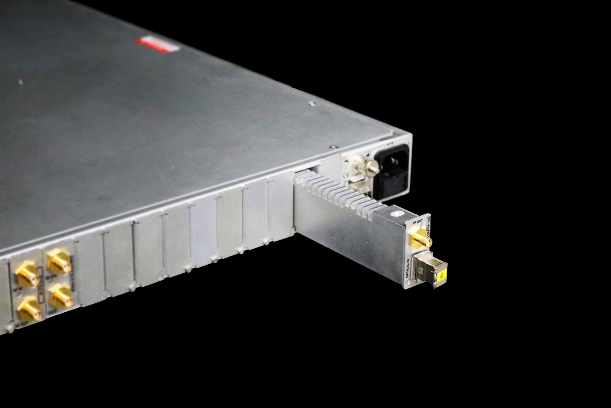
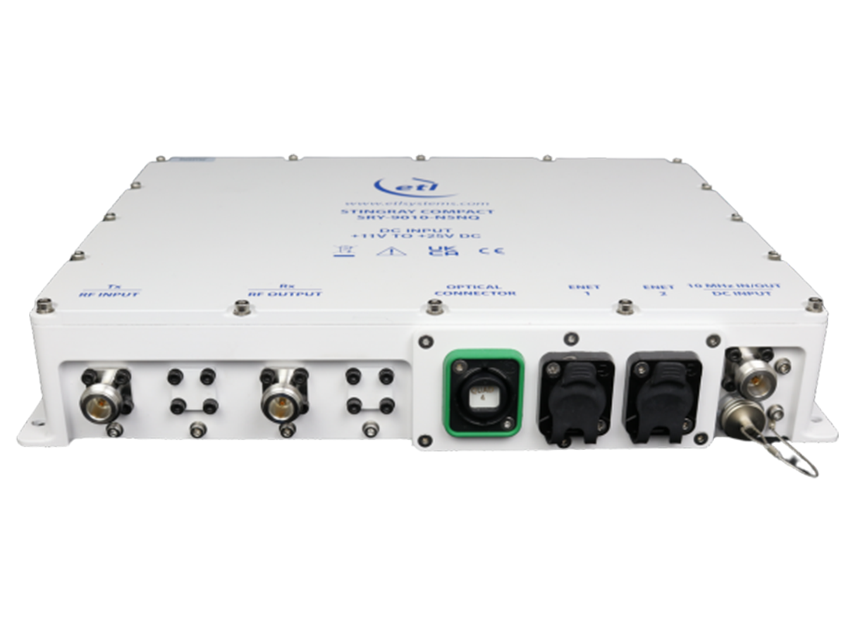
At ETL Systems, our StingRay RF over Fibre range includes L-band, S-band and wideband fibre links, alongside modules for 10 MHz, timing signals and Ethernet over fibre. Current StingRay modules are also available with manual, fixed, and automatic gain-control modes.
The right configuration depends on how those RF and optical requirements fit together, rather than on fibre distance alone.
If you are planning a new link or reviewing RF transport across an existing satellite ground system, contact us to discuss your RF, optical, and deployment requirements.