
Frequency Converters
Streamline your operations with advanced frequency converter solutions. Falcon2 enables a new level of capability and adaptability in SATCOM; delivering reliable, stable, and precise frequency conversion with redundancy in a single 1U chassis.
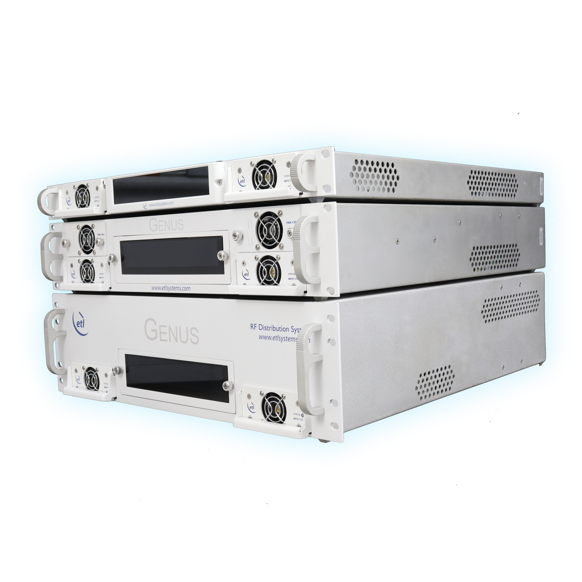
Compact, modular, and future-proofed RF frequency converter solution
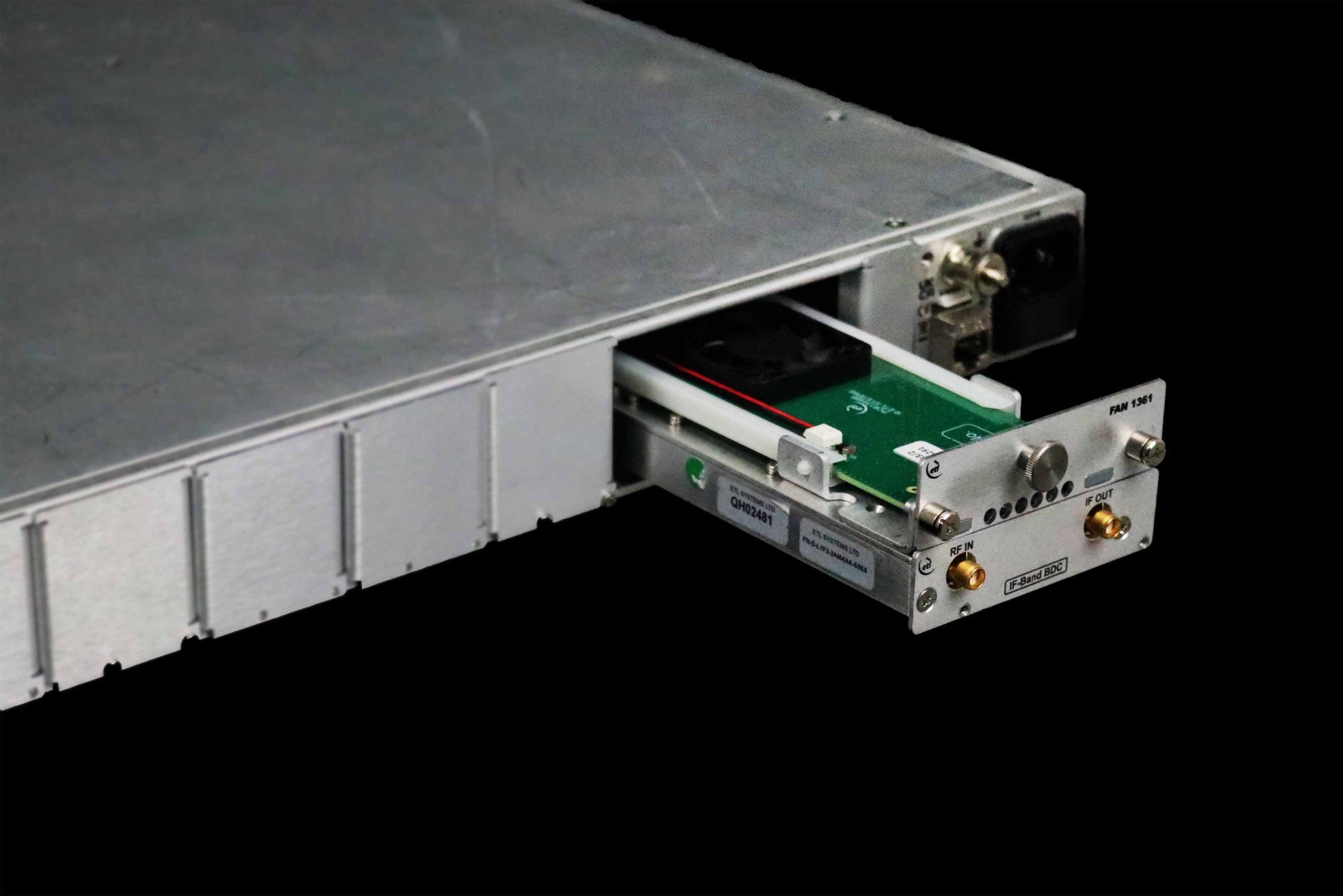
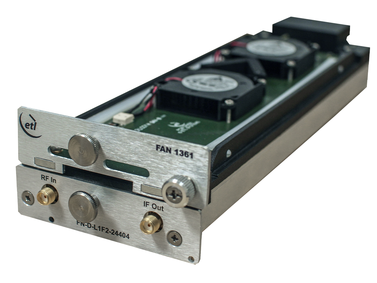
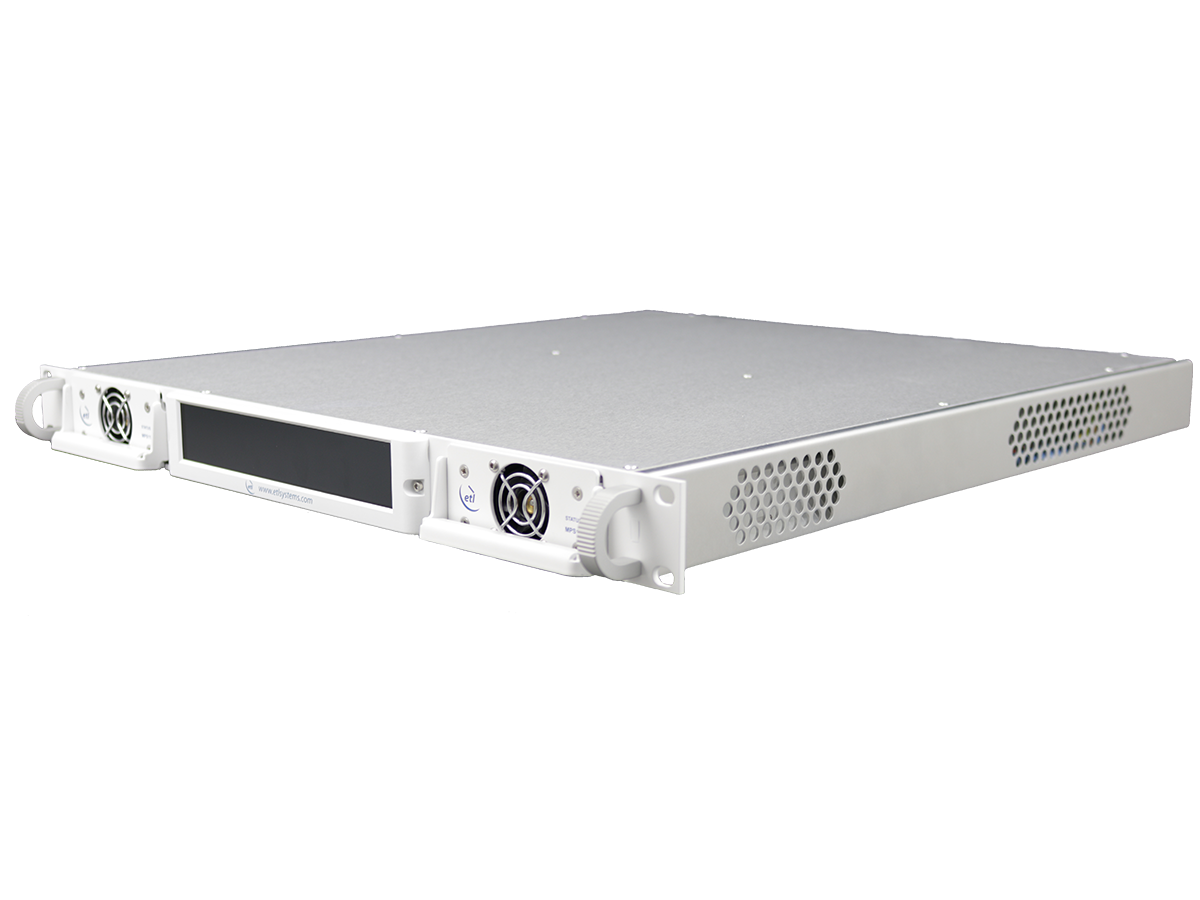
ETL’s Falcon2 Frequency Converter range includes agile or block upconverters and downconverters, housed in a compact GENUS modular chassis.
Falcon2 is the preferred choice for teleports, earth stations, satellite operations, government and defence applications, telemetry, tracking, command, and high-resilience scenarios.
Multi-Band Frequency Coverage
Operating across Ka, Ku, K, C, X, L and IF-band spectrum
Modular Adaptable Configurations
Available as indoor or outdoor units, with modular chassis for flexible deployment
Unmatched Capacity in 1U
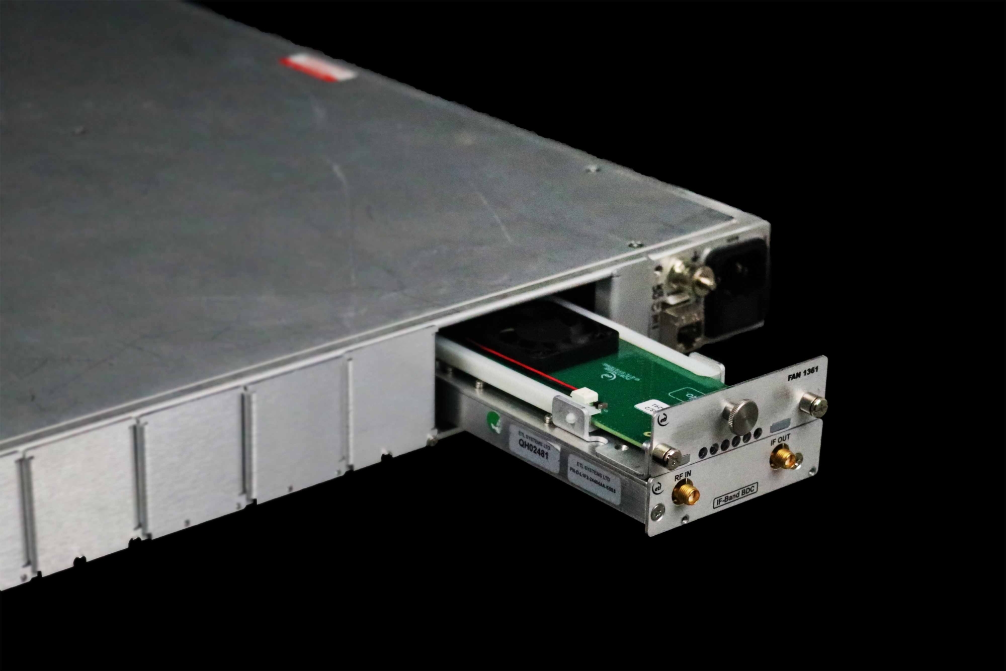
Market leading capacity – 4 hot-swap frequency converters within a 1U chassis
Frequency Converters
Ready to make a purchase or explore your options? Speak with our team today to receive expert advice, tailored recommendations, and clear next steps.
Get in touchRelated products
Deployed in deep space gateways around the world
GNS-106-1U
GENUS 1U modular chassis
1U chassis for modular GENUS ecosystem; mix and match RF functions within a single housing
GNS-186-1U
GENUS 1U modular chassis
1U chassis for modular GENUS ecosystem, with 100MHz internal reference
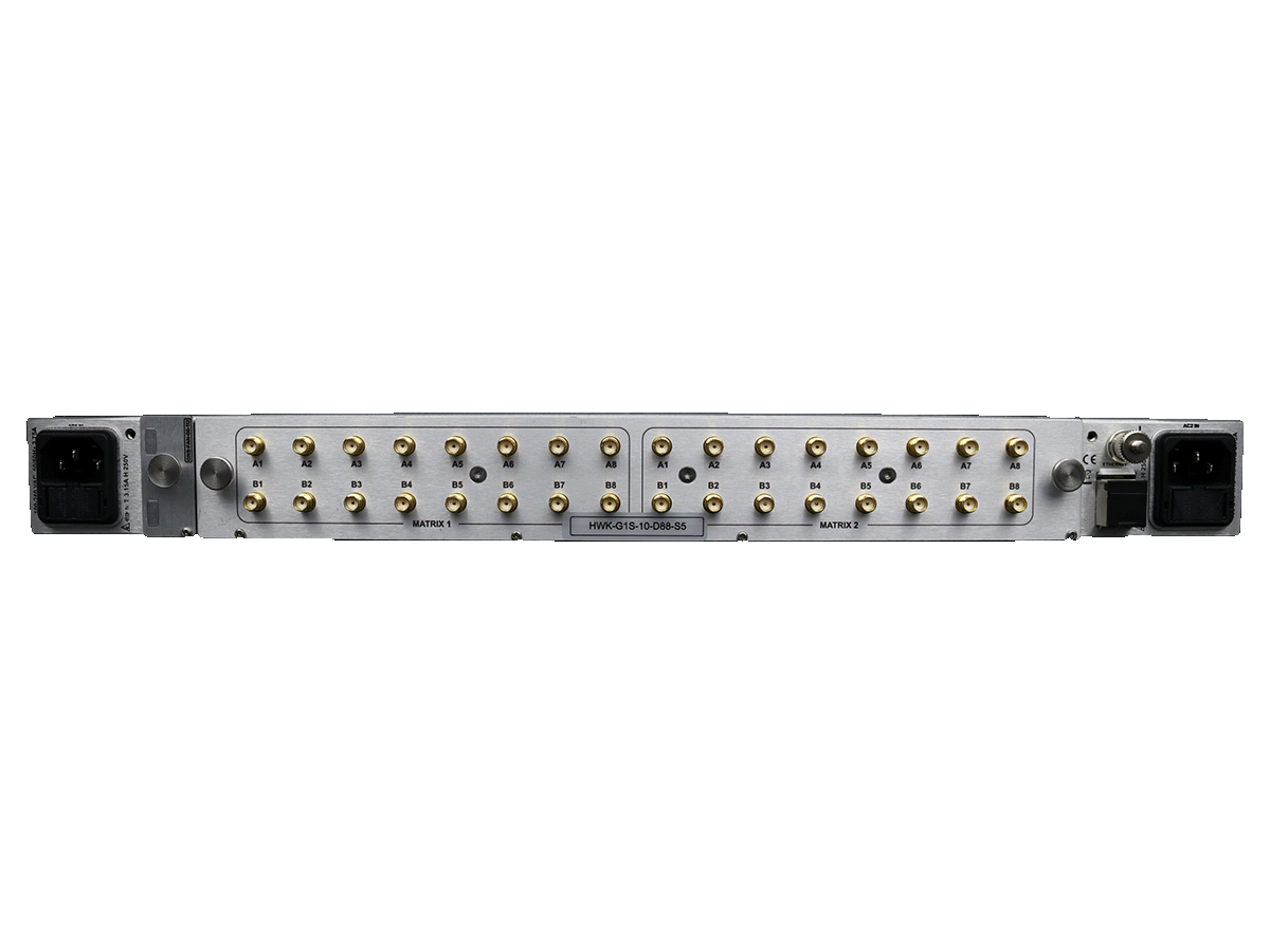
HWK-G1S-10-C88
HAWK 8x8 combining matrix
500-2450MHz extended L-band range, with unity gain
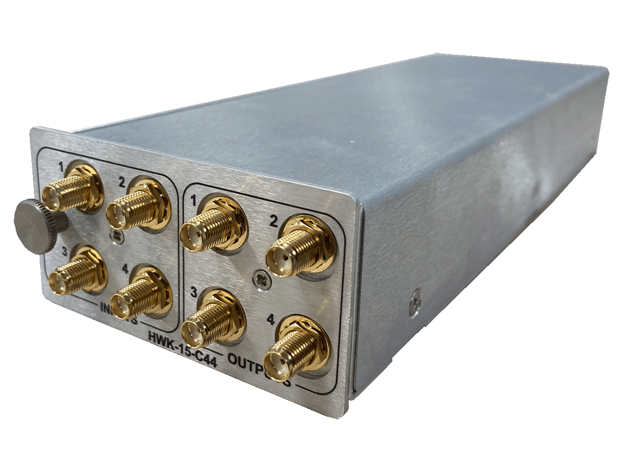
HWK-G1S-15-D44
HAWK 4x4 distributive matrix module
500-3150MHz extended L-band range, with unity gain
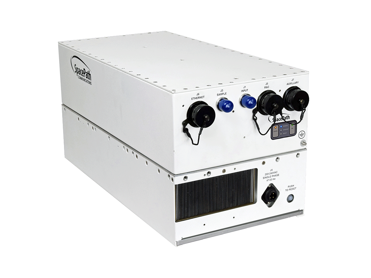
STA5475
SPACEPATH 750W DBS-band TWTA
With variable gain, optional BUC/lineariser and frequency range options

STA74125P
SPACEPATH 1250W peak DBS-band TWTA
With variable gain, optional BUC/lineariser and frequency range options
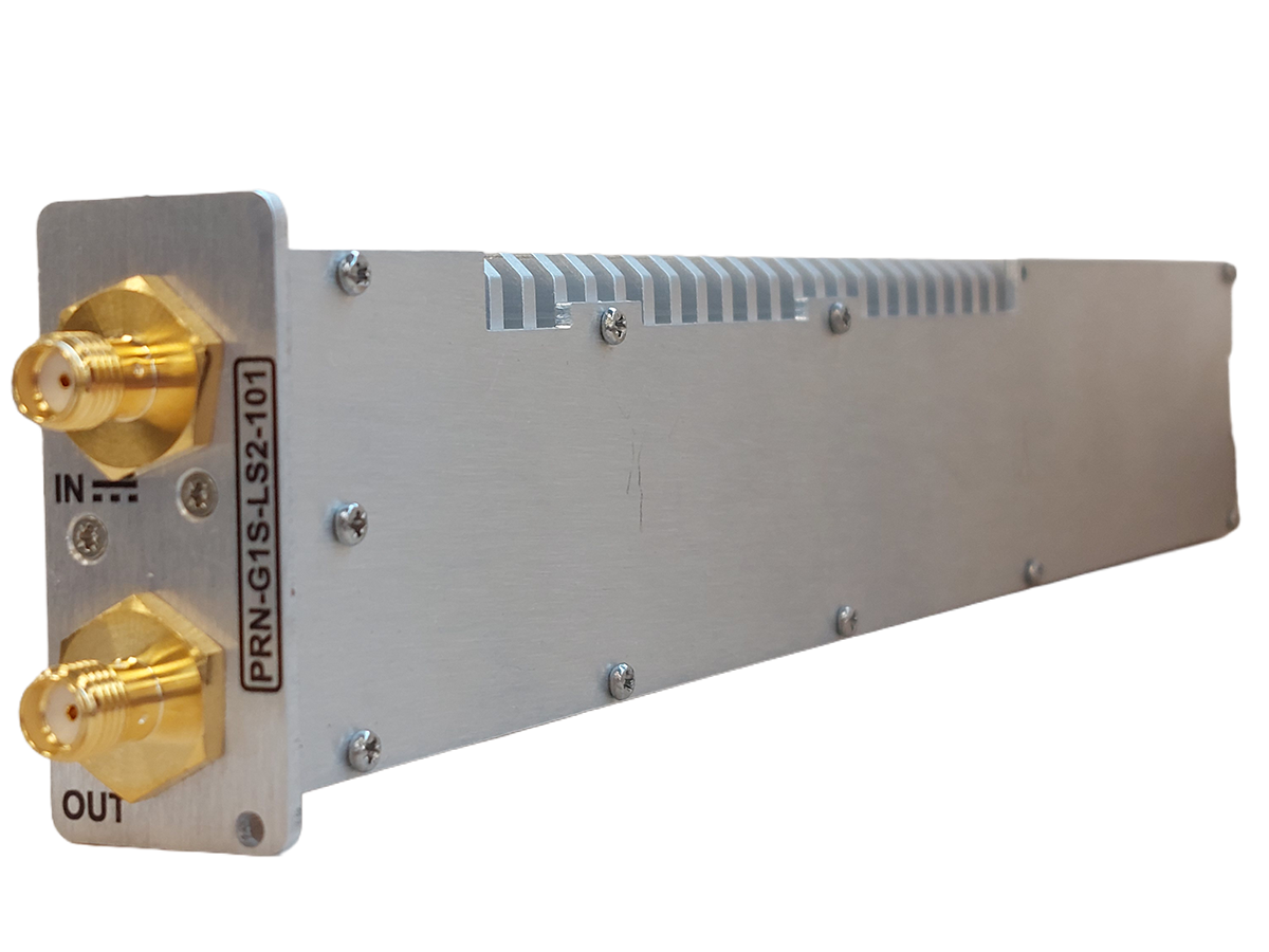
PRN-G1S-LS2-101
PIRANHA LNB 10MHz/DC injection module
For use with modular GENUS ecosystem, selectable 13/18V 22kHz, up to 500mA
GENUS modular system
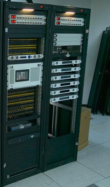
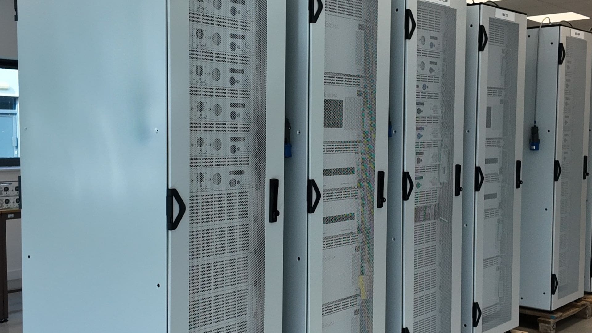
The latest advancement in chassis technology, offering a compact, modular, and flexible solution for growing teleport operators. Available in 1U, 2U, and 3U rack sizes, and in outdoor unit (ODU) versions, the GENUS chassis can accommodate up to 17 RF distribution modules, allowing operators to customise their setup according to their specific needs.
This modularity provides a high degree of adaptability, making the GENUS smart chassis an ideal choice for operators looking to scale their operations efficiently and effectively. The smart chassis concept allows for the housing of multiple RF modules within the same shelf, providing space savings, reduced costs, and increased rack space efficiency.

Modular, configurable chassis
The GENUS chassis integrates StingRay RF over fibre, Falcon frequency converters, Alto amplifiers, digitisers, switches, splitters, 10 MHz injection, and small RF matrices/routers, all within a single indoor or outdoor chassis.

Flexibility
Operators can configure the GENUS chassis to meet their exact RF distribution needs, ensuring optimal performance and efficiency.

Cost reduction
By providing space savings and offering hot-swappable components, the GENUS range reduces running costs and enhances maintenance efficiency.

Unified protocol and commands
Consistent protocol and software commands across multiple chassis types, with standardised webpage across all platforms for ease of use. Additionally, uses the same power supply units (PSUs) and central processing units (CPUs) across different chassis types for commonality of spares.
Agile & Block Up and Down Converters
- Flexible module configurations, allowing multiple frequency converters to be housed within a single GENUS chassis. These can be configured as all upconverters, all downconverters, or a mix of both, based on your requirements.
- Redundancy configurations such as 2+1 and 1+1 are available within the converter chassis, eliminating the need for a separate chassis for redundancy.
- The system also features field-serviceable and replaceable modules, including hot-swappable dual redundant power supplies and a field-replaceable CPU.
- Capability for customisation to bespoke requirements (minimum order quantity applies)

Block vs. Synthesised (Agile) Converters
A fundamental choice in converter selection is between block (fixed LO) and synthesised (agile) types:
| Feature | Block Converter | Synthesised (Agile) Converter |
| LO frequency | Fixed — set in factory | Electronically tunable, user-selectable |
| Output frequency range | Fixed — translates entire input band as a block | Variable — operator selects centre frequency |
| Frequency step size | N/A (block translation) | Typically 1 kHz or finer |
| Phase noise | Generally better: simple fixed oscillator | Slightly Higher: synthesiser PLLs add phase noise |
A block converter with a fixed LO at 9.75 GHz, for example, will translate the entire 10.70–11.70 GHz Ku-Band downlink to 950–1950 MHz L-Band simultaneously. An agile converter operating over the same RF band allows the operator to tune the LO so that only a narrower band of interest is centred within the IF passband, useful when monitoring individual transponders or performing spectrum analysis.
Single vs. Dual Conversion
A single-conversion converter uses one mixer stage. This is simple and cost-effective but may suffer from image or LO contamination when the IF is a large fraction of the RF (because the image is close to the RF). A dual-conversion converter uses two cascaded mixer stages with an intermediate frequency between them. This allows:
- First conversion: Translates the RF to a high intermediate frequency (IF1), ensuring the image frequency for the first conversion falls well outside the input filter.
- Second conversion: Translates IF1 to the final IF, again with adequate image separation.
Dual‑conversion topologies require two LOs and two sets of filters, increasing cost and complexity. ETL’s Falcon2 converters use a dual‑conversion architecture where dictated by the frequency plan, delivering superior image rejection and supporting applications where performance is non‑negotiable.
| Parameter | Single Conversion | Dual Conversion |
| Complexity | Low | Higher |
| Cost | Lower | Higher |
| Image rejection | Limited by input filter | Excellent — image well out of band |
| LO count | 1 | 2 |
Checklist for Ground Segment Engineers
- Identify the satellite RF band (C, X, Ku, K, Ka, Q, V)
- Confirm whether uplink (Earth-to-Space) or downlink (Space-to-Earth) or both are required.
- Determine the IF/L-Band interface required by the modem or associated equipment (70 MHz, 140 MHz, L-Band 950–1950 MHz, etc.).
- Confirm the full RF frequency range and the required instantaneous bandwidth.
- Determine whether a block converter or synthesised (agile) converter is required.
- Noise Figure: Determine the system noise budget and maximum permissible NF contribution from the converter.
- Phase Noise: Check the maximum tolerable phase noise mask at relevant offsets (1 kHz, 10 kHz, 100 kHz). Higher-order modulation requires lower phase noise.
- Linearity (P1dB / OIP3): For multi-carrier operation, determine the maximum combined input power and required back-off. Calculate the required OIP3 from the number of carriers and the permissible IM3 level.
- Gain and Gain Flatness: Confirm the output level matches what downstream equipment expects, and that gain flatness is sufficient for the occupied bandwidth.
- Spurious outputs: Check regulatory emission masks and adjacent transponder separation.
- Image Rejection: Ensure adequate image suppression, particularly for wide-IF applications.
- Frequency Inversion: Confirm whether the modem can compensate for spectral inversion, or ensure the converter is non-inverting.
- Connector types: Confirm RF connector type (SMA, 2.92, etc.) and IF connector requirements.
- Impedance: Standard 50 Ω throughout; verify VSWR/return loss.
- 10 MHz reference: Confirm whether an internal or external 10 / 100 MHz reference is required and the reference signal quality (phase noise, stability).
- Remote monitoring and control — Confirm required interface (Ethernet, SNMP, etc.)
- Physical: Confirm rack unit height, depth, and slot requirements.
- Determine the required system availability target and identify if redundancy is needed.
- Select 1+1 (one active, one standby) or 2+1 (two active paths, shared standby).
We support customers in over 130 countries, with over 40 years of experience in design and manufacturing.
1/3

Engineered for Reliable RF Performance
Every RF environment is unique. Our expert engineers design and manufacture systems tailored to your specifications — ensuring unmatched scalability, reliability, and performance.