By Scott Reid, ETL Systems
Satellite ground stations and teleports require an effective transmission method to transmit radio frequency (RF) signals between the antennas and signal management equipment centres. Conventionally, these signals are transmitted by coaxial cable — where transmission losses are high, and signal quality can be degraded by distance. Thus, in long distance (or high capacity) signal transmission, RF over fibre via coarse wavelength division multiplexing (CWDM), or dense wave division multiplexing (DWDM) are becoming more important.
However, there remains a great deal of confusion between the two methods. What is the difference between CWDM and DWDM? This article aims to clarify the differences, as well as discuss the challenges associated with both technologies.
RF Signal Transportation
RF over fibre (RfoF) technology is an attractive solution to provide low loss and higher bandwidth for inter-facility links. Standard satellite signal frequencies usually are sent in the C- band (3-8 GHz), Ku- band (12-18 GHz), or Ka- band (26-40 GHz). At the ground station antennas, RF signals received from satellites are down converted by the low noise block (LNB) down converter to L-band (950- 2150 MHz) or an extended L-band (850- 2450 MHz), then transmitted via coaxial cables. L- band is easier to handle and process than other frequency bands and can be operated with less expensive RF equipment.
Down converted L-band signals are transmitted from an LNB to the receiver or decoder, via an inter-facility link (IFL), for processing and decoding. Coaxial cables can be used for short links, where the distance between LNB and control unit typically is less than 100 metres. Longer coaxial cable runs mean a reduction in signal quality, degradation of the signal-to-noise ratio, and greater signal attenuation, leading to a need for costly amplifiers to compensate for these losses.
CWDM
CWDM uses a multiplexer to combine optical signals on a single fibre by using different wavelengths for each signal. The operating wavelengths range from 1271 nm up to 1611 nm, with 20 nanometre channel spacing, specified in ITU-T G.694.2 recommendation. There are 16 optical channels altogether; however, in reality, only 8 optical channels can be used, as the lowest wavelength channels are avoided due to high attenuation losses. Effectively, the number of channels is further reduced because of the high transmission losses around the water peak at 1380 nm, as defined in standard ITU-T G.652. That said, most commercial CWDM systems use 8 wavelength channels, from 1470 – 1610 nm.
The wider channel spacing (20 nm) in the CWDM system makes it much cheaper to develop system components, such as laser diodes and wide passband filters, versus DWDM systems, where such components need to be more finely tuned and precisely calibrated . CWDM also allows the use of uncooled lasers, which are easier to manufacture due to the wider tolerance of wavelength which can be accommodated when compared to DWDM.
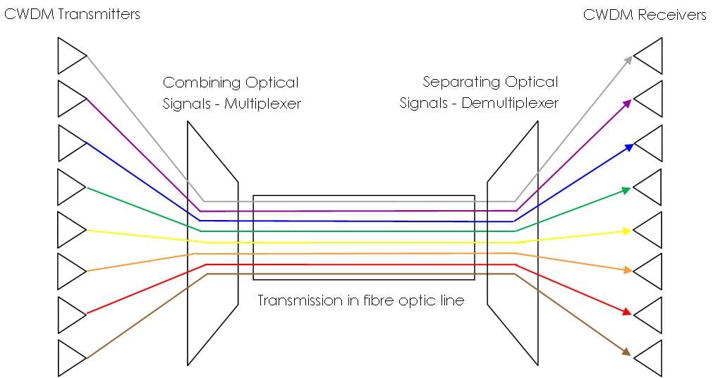
Wavelengths are combined in a CWDM multiplexer and separated at the other end in a CWDM demultiplexer. The multiplexer and demultiplexer are passive and bi-directional, so the same device can be used as both multiplexer and demultiplexer.
The low cost and simplicity of CWDM makes it a good choice for the transmission of RF signals. However, it is only able to transmit signals up to about 40 kilometres. Beyond that distance, you start to get significant optical loss. To combat that optical loss, you will need an Erbium-Doped Fibre Amplifier (EDFA), an optical amplifier, to boost that signal. EDFAs are inherently narrow band; and can only cover the range from 1530-1565nm; which makes them unfeasible for use within CWDM systems, where signals are widely spaced. This is one of the reasons why we need DWDM.
DWDM
The reason so much confusion exists between CWDM and DWDM is that both technologies combine multiple optical signals, on a single fibre, using different wavelengths. For DWDM, these are combined and separated using DWDM multiplexers and demultiplexers — the same technique as CWDM. The main difference comes down to the laser technology used.
DWDM creates a much narrower spectrum of light, means wavelengths can be combined at spacings of less than 1 nanometre. The frequency grid ranges from 12.5 GHz (0.1 nm) – 100 GHz (0.8 nm) in the operating wavelength between 1530 nm – 1625 nm. This allows a far higher number of wavelengths to be combined in a narrow optical bandwidth. Rather than just 8 optical signals, DWDM can accommodate as many as 40 multiplexed channels for 0.8/0.4 nm (100 GHz/ 50 GHz) channel spacings.
The transmission distance of DWDM channels can be extended easily, for hundreds of kilometres, using optical amplifiers to compensate for losses and boost optical power. Use of an EDFA enables DWDM to handle RF signals over much greater distances than are possible with CWDM, without suffering significant optical loss.
However, DWDM laser technology is more expensive than CWDM, as it requires more stable wavelength sources. The increasing cost of the DWDM transmitter is mainly due to the high cost of the laser diodes, and the feedback cooling operation to maintain the wavelength stability.
Considerations: When to use cwdm or dwdm?
When transmitting RF signals over fibre, a number of considerations will determine which technology makes the most sense. In a simple setup, where the fibre needs to take one signal over an unimpeded and short distance, a standard fibre link will make the most sense. When deciding between CWDM and DWDM, it comes mainly down to the number of signals to be transmitted and the distance the signals need to travel, which will have an impact on signal loss.
Optical Budget
An optical budget is the maximum optical signal loss over which the required RF performance of the link can be maintained. For standard links of 1310nm, you can generally expect a loss of around 0.4 dB/km. For CWDM, we should anticipate a loss of around 0.28 dB/km at 1550 nm. Therefore, optical budget can be assumed to be 4 dB for standard links (i.e., <10 km) and 14 dB for CWDM (i.e., <50 km) dependent upon laser output power and receiver sensitivity.
However, we need to take into account other optical losses to gain a true understanding of the distance each method can achieve. Connector losses and patch panels can lose up to 0.5 dB per connection. Fibre splicing losses can be up to 0.2 dB. Optical splitters tend to cause a signal level attenuation of 3 to 4 dB per 2-way split. A CWDM Mux / Demux will lose a further 2.5 dB to 6 dB, depending on capacity. All the optical link losses need to be added to/subtracted from the optical budget to calculate an accurate achievable distance.
That all said, you will need to use DWDM when only a single fibre is available and there are more than 8 channels to be transmitted, or when the optical signal loss exceeds the optical budget. Optical amplification will compensate for optical losses and maintain the required the optical power at the receivers.
Dark Fibre
Another major consideration when sending RF signals over fibre — whether by standard link, CWDM, or DWDM — is the use of dark fibre. Most long fibre transmission paths use dark fibre (i.e. fibre that is rented), usually from a telecoms operator.
Dark fibre is extremely useful, because the cost and effort of laying your own fibre is far too high for most companies. However, its use comes with its own set of challenges, the first being that the condition of the fibre is not known. Second, many telecom operators do not understand the requirements for analogue RF over fibre signal transmission. It can be very difficult, especially in certain parts of the world, to make it clear that analogue RF over fibre signals need to be sent on a dedicated fibre, not shared with other data communications. If that directive is not followed, it can be detrimental to the signal. It is therefore important to understand as much as possible about the state of the fibre link to protect that signal.
Chromatic Dispersion
Chromatic dispersion is a phenomenon occurring naturally in all optical fibres, wherein the different wavelengths begin to disperse. For RF over fibre links, chromatic dispersion is negligible enough to cause no problems in most instances. However, chromatic dispersion becomes problematic when the distance approaches 100 km, or when certain high-order modulation schemes are used. For links approaching this distance, you therefore need to consider using dispersion compensating fibre (DCF) to reduce the effect.
EDFA
As mentioned earlier, EDFAs are used to overcome excessive optical loss down long fibre runs. If an EDFA is required for multiple optical signals, then DWDM technology must be used, as the CWDM wavelengths are not fine enough. Depending upon the link properties, an EDFA could be deployed at different positions along the fibre run.
Why Use Fibre For RF Signals?
Perhaps one question left unanswered is why, when satellite technology is perfectly designed for sending RF signals over massive distances, do we even need to use fibre for RF signals?
The main driving force is the trend toward high-throughput satellites (HTS) and Ka- band technology. Operators often are deploying diverse sites to combat potential rain fade, which can cause severe signal losses in extreme weather conditions. The distance of diverse sites away from the main site depends on the location. In some places, weather is so localised that 40 km may be enough. In most scenarios, we are more likely talking between 70–100 km to be in a different weather pattern. The signals need to pass upstream and downstream between main and backup antennas in the same condition, and DWDM currently is the only way to ensure that.
So, if your antenna and control centre are just across a small field and you only have a couple of feeds, use a standard non-multiplexed RF over fibre link. If you are crossing distances between 10km and 50km, use CWDM. However, if you need something that carries signals over 50km, DWDM is an extremely viable, even vital, technology.